
You’ve got all your kit, or you’re planning to, and you want to see how it all goes together. For the most part it’s fairly obvious, but there are a couple of things I saw along the way that I thought were of note.
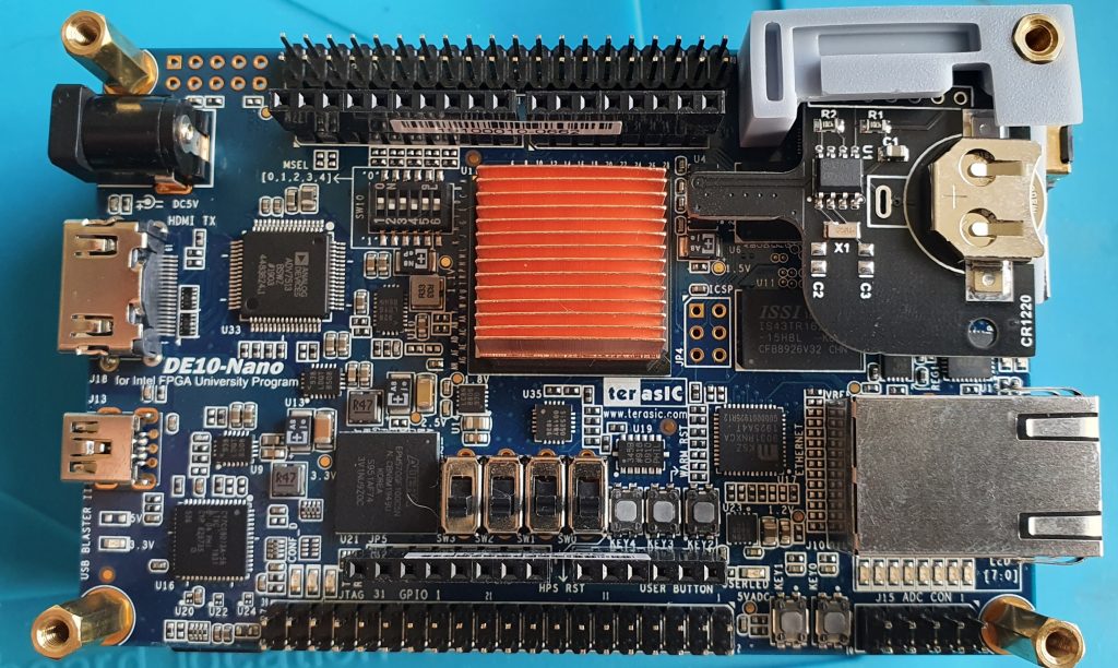
Heatsink
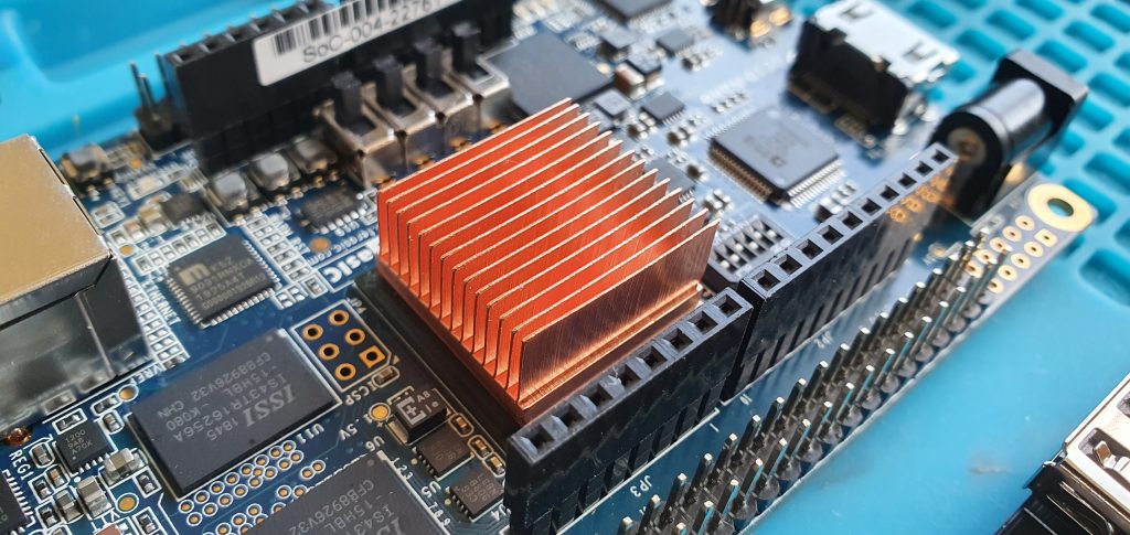
I would install this as a first step. The sticky heatpad on the base of the heatsink needs a reasonable amount of pressure to fully adhere. I’d do this as a first step so you do not cause the board to flex too much.
Also, note the orientation of the fins. There are headers above and below the CycloneV which can impede airflow. Orientating the fins lengthways along the board allows air to flow more freely to the edges of the board.
Having built a couple now, I’d advise building the rest from the bottom up.
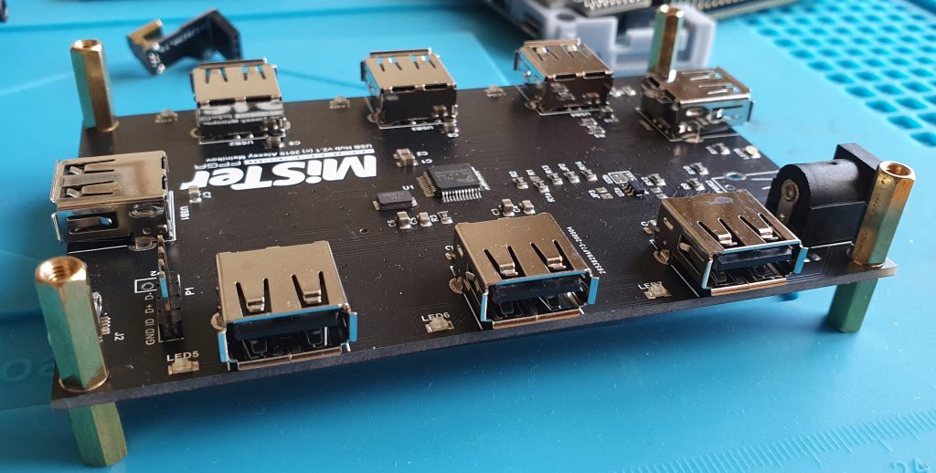
USB Hub
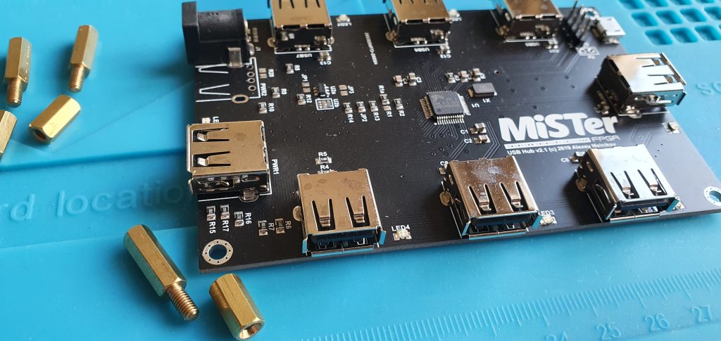
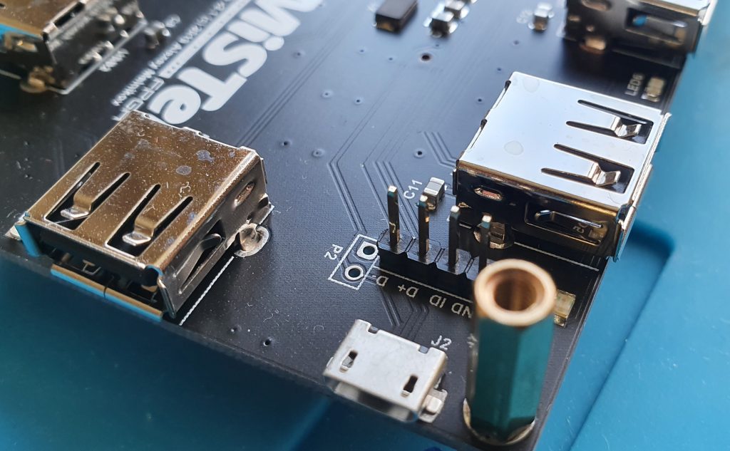
The USB hub comes with standoffs, four sets of female/male and female/female. At each corner, put the threaded part of the standoff through from upper side to lower.
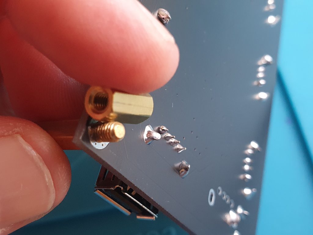
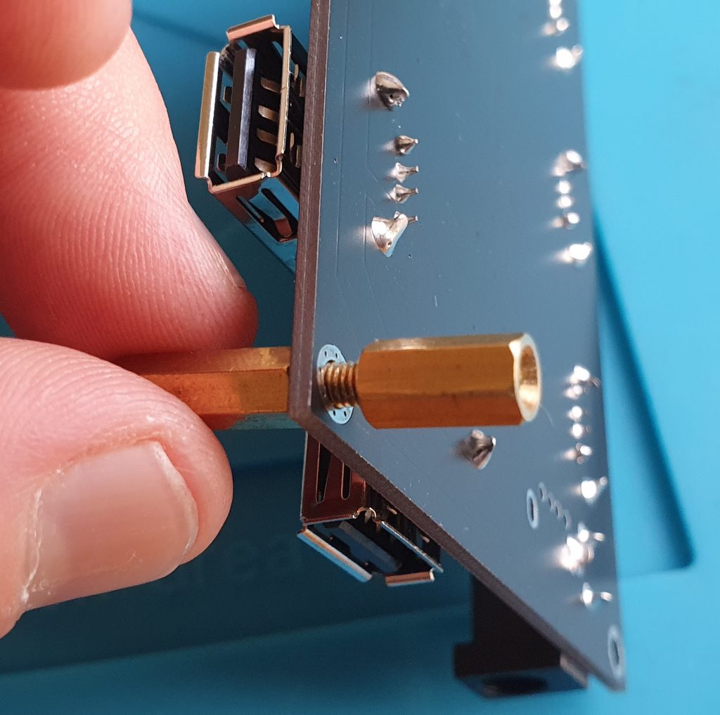
Attach the female/female standoff to the thread, and repeat at each corner. These act as feet for the stack. Ideally use a hex driver, but a small pliers will do. Just bear in mind not to overtighten and damage the board.
RTC
You can add the RTC now or after attaching the DE10 board to the top of the USB hub. Ideally I’d recommend the latter. I did it first here just for clearer pictures.
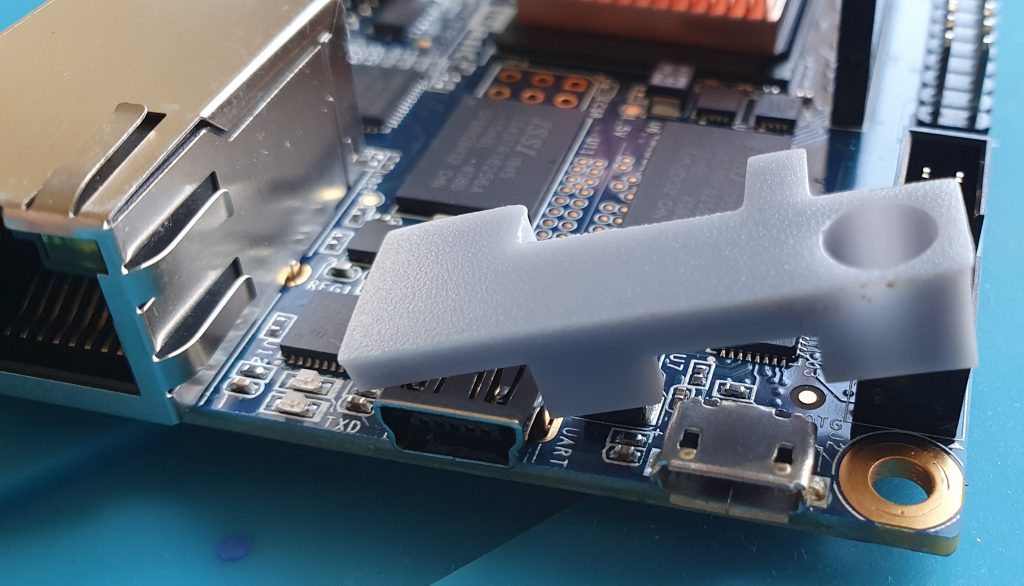
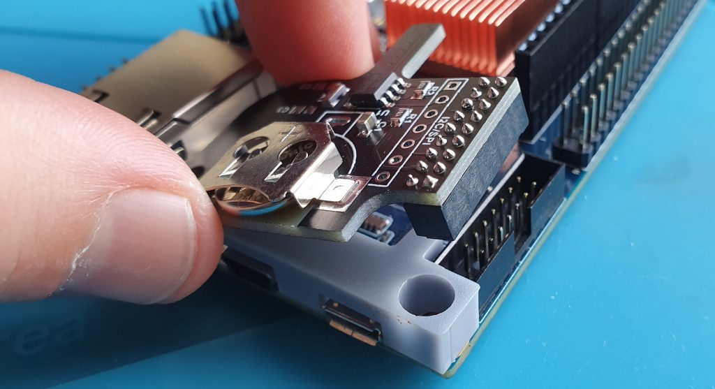
Grab the DE10 and drop the shim with the cutouts for the USB ports in first, then plug the RTC module into the LTC 2×7 header on the edge.
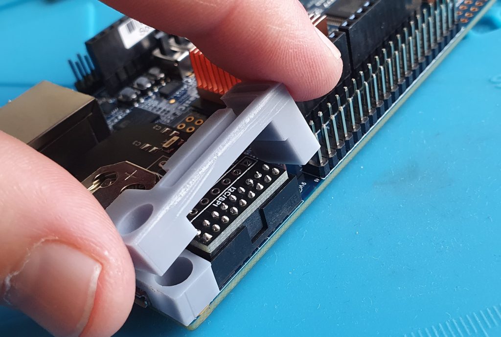
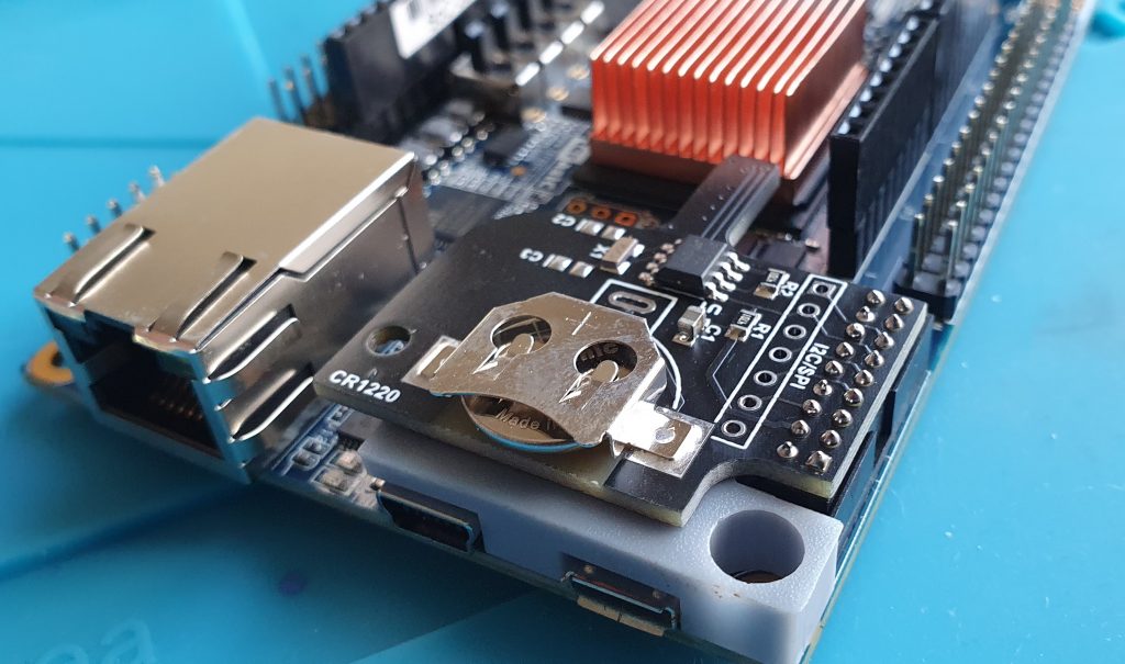
Next slot the other shim above the RTC module. As you can see it is quite a snug fit.
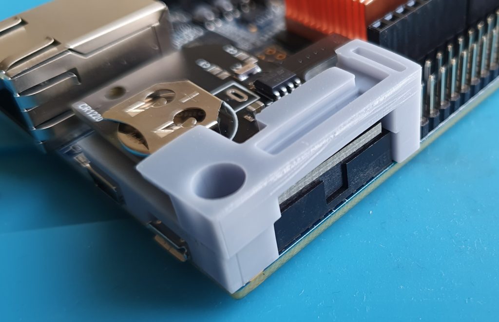
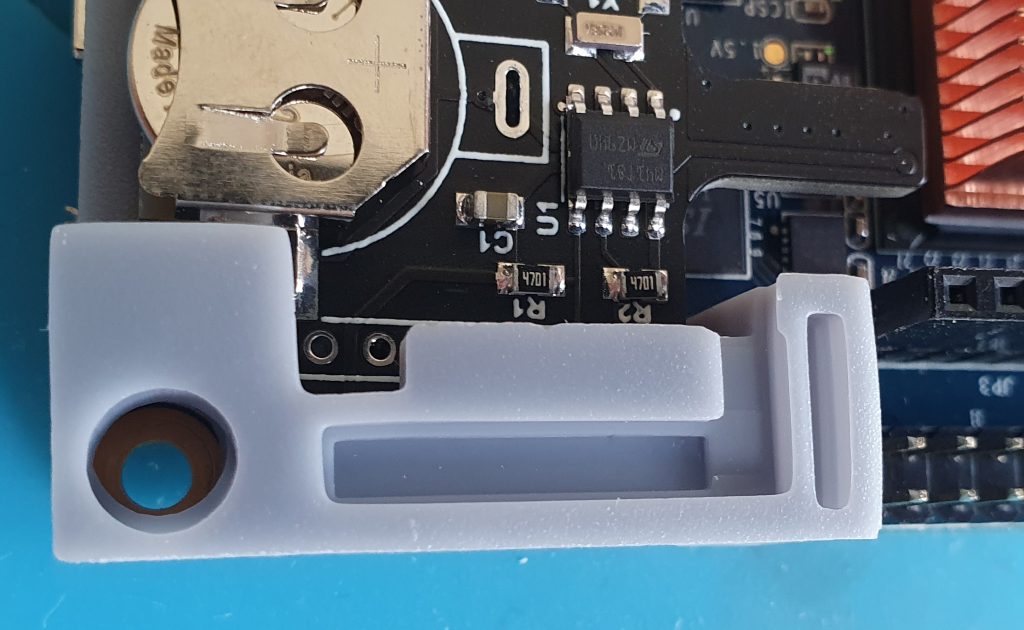
Once in properly, the holes in both shims should line up with the mount hole in the PCB. The gully you can see in the shim is to accommodate solder points on the bottom if the I/O board.
Mounting the DE10
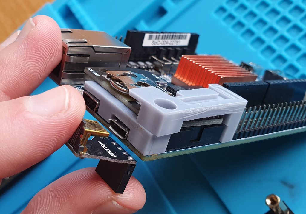
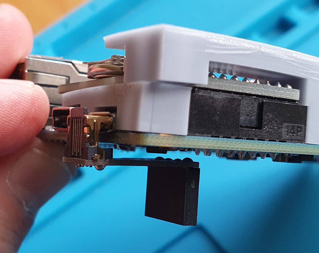
Slot the USB bracket connector into the micro USB OTG port on the DE10. This is located right next to the RTC module and header and itself has a header connector that reaches under the board.
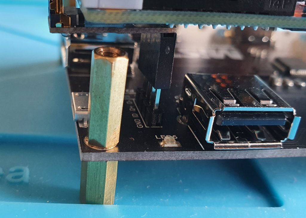
In one corner of the USB hub is a USB2 header. Line up the header connector dangling off the bottom of the DE10 with these pins. At this point you’ll be tempted to push down, but don’t do this. It shouldn’t damage anything, but I’d rather not grind the USB bracket against the bottom of the DE10. I held the bracket away from the DE10 with a plastic spudger, but you could just as easily use a lolly stick or fingernail.

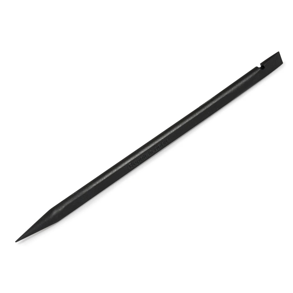
Spudger Lolly stick Fingernails

DE10 prep
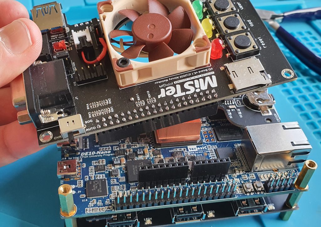
Around now you should have this:
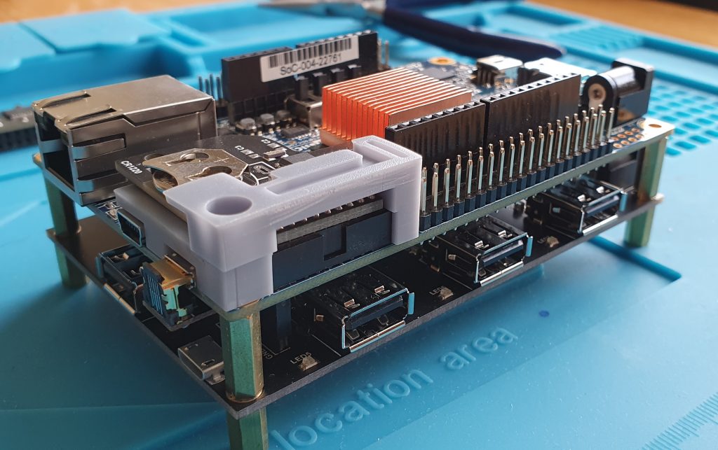
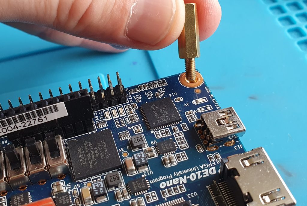
Take the remaining four standoffs, the four you removed from the DE10 to remove the acrylic shield. Screw these in to each corner of the DE10, again using a hex driver or pliers, but being careful not to overtighten.
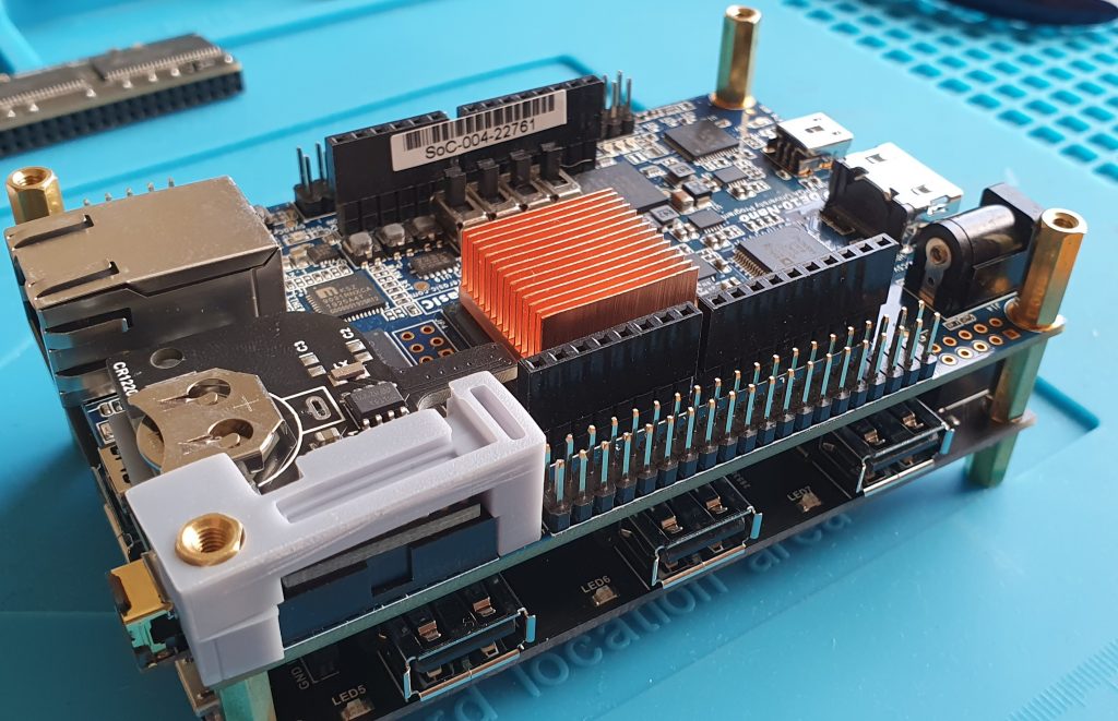
So now you have this:
I/O Shield
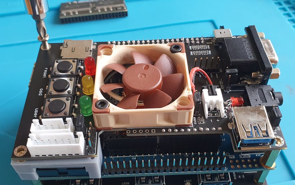
Now we attach the topmost PCB, the I/O board. As mentioned previously, this is the analogue v6.1 board but the digital board is much the same in attachment.
Take your I/O board and line it up with the DE10.
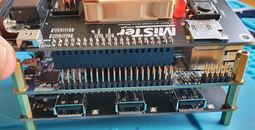
The pins on one side line up with the 2×20 GPIO pins, and on the other side line up with a 1×6 header connector so it should be clear if you have it the wrong way around.
Gently squeeze both sides together and the two boards should mate. If you’re not sure, stop. Better to stop and check and maybe straighten a bent pin than break one off and cry.
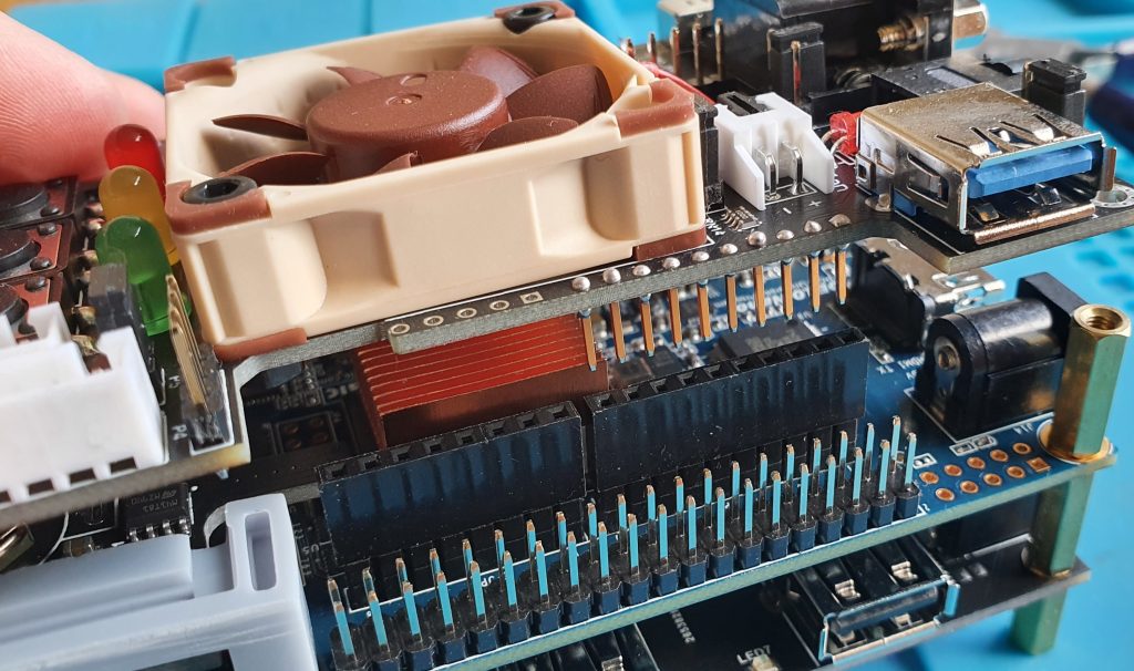
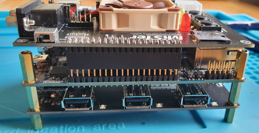
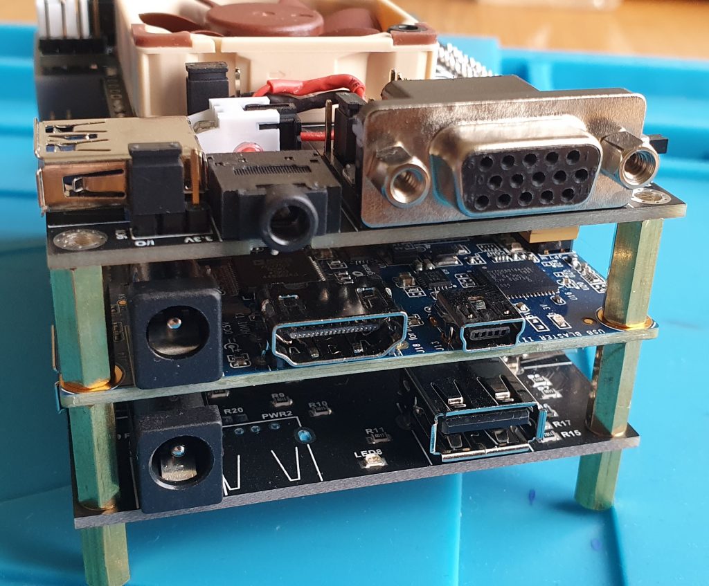
For reference, you can see the barrel jacks on the USB hub and DE10 and the VGA on the I/O board are all on the same side.
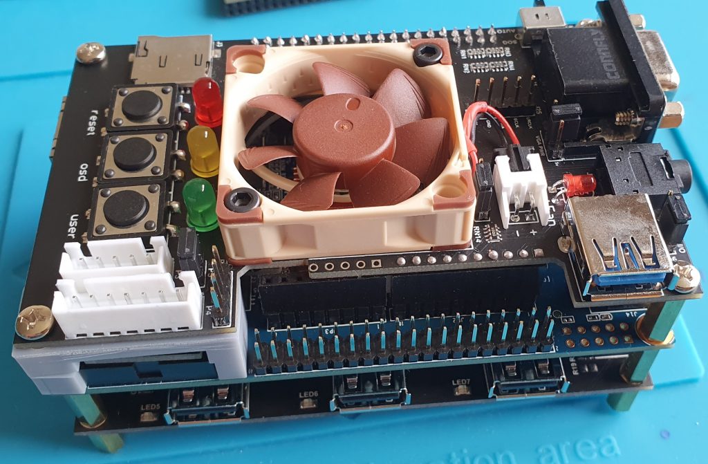
Now take the screws you removed earlier when you removed the acrylic plate and use them to screw down the I/O board. Again, not too tight.
RAM
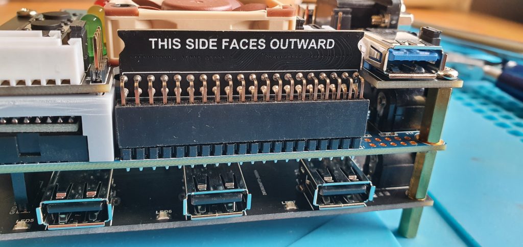
Lastly, there’s the SDRAM board. Attaching it is pretty straightforward, simply take note of the obvious THIS SIDE FACES OUTWARD stenciling and make that side face outward.
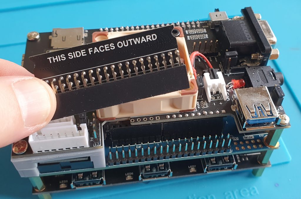
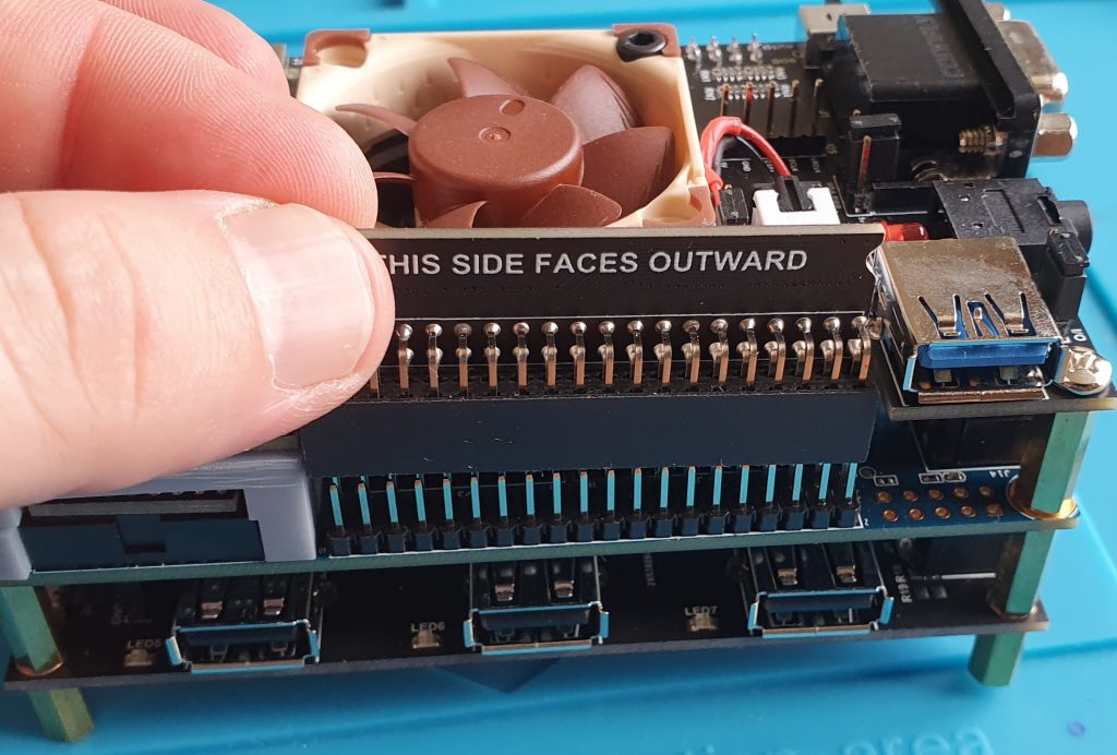
Of note here is that by far this was the stiffest attachment in my build. Yours may be different, but I was very careful to apply even pressure across it’s length and supported the DE10 from beneath.
One other thing is that the module is quite tall. When installing, and thereafter when in use, there is a small risk of the SDRAM module being pushed to the side and bending pins with it. Just be careful when installing and have nothing that can fall on your MiSTer nearby or any cables to pull against it when in use and you should be fine. But as that’s a 40mm fan spinning on top of bare PCBs, that should go without saying.
You should now have a built MiSTer system. Next time, we move on to the initial config.
1 thought on “MiSTer 1.2: Building The Thing”